Circuit Board design and testing for the Color Doppler Analog Signal Processing board:
Ultrasound machines use a transducer (the part that the ultrasound technician places against the patient), which is essentially a sound-wave antenna, to inject sound waves into the patient, and whenever the sound waves encounters a change in density, some of the sound energy is reflected back and can be received by this same transducer. The sound beam is electronically 'steered' to point in different directions, so by recording the return echo strength at different angles, and noting the time delay (longer delay means further into the body), the machine can display a greyscale image of the density of tissue in the patient.
When the transducer receives the return echoes of the sound energy, in addition to noting the time delay and strength of the echo (which is used to display the greyscale density image), you can also note any shift in the frequency of the signal, which is caused by Doppler shift if the sound waves encounter anything moving within the body. The only thing that moves quickly enough to cause a Doppler shift is blood flow, so this information can be used to overlay a color image onto the density image showing where blood is flowing, in what direction, and the speed of the flow, which is very useful medically for diagnosis.
The technique involves something called In-phase and Quadrature-phase sampling (IQ Sampling) where the incoming signal is mixed with a signal of the exact frequency transmitted and also one shifted 90-degrees in time. This technique provides more information than simply noting the strength of the return signal, including detection of any shift in the frequency of the received signal and also whether the shift is towards higher frequencies (meaning the blood is flowing towards the transducer) or towards lower frequencies (meaning the blood is moving away from the transducer). The amount of deviation in frequency is eventually encoded in the vibrancy of color with towards and away coded as either red or blue so the radiologist can see the direction of the blood flow.
This was the first time I had really designed a circuit board, especially of this complexity, and there were many unique challenges. The outgoing transmitted signal had to be quite strong, so the transducer elements were pulsed with fairly high voltages (around 100V), but then these same transducer elements had to 'listen' for return echo signals that were very faint - electrically only around 1/1000th of a volt. We also had to use very high-speed Analog-to-Digital converter chips (A/D chips) and the high clock rates for these generated high levels of noise, which make it particularly difficult to detect faint voltages as signals. In fact the A/D chips were designed to be used on circuit boards which had completely separate ground planes - one for the analog side and a separate ground plane for the digital side to try to help keep the digital clock noise out of the analog circuitry.
So I designed the Color Doppler Analog circuit board from scratch and also the test rig and test software that would be used to test this board in production. This circuit board did the analog signal processing and sampling into a high-speed digital data stream and then a second circuit board would receive this board's output and perform digital signal processing to extract the frequency information to ready it for the display portion of the ultrasound machine. The test rig for the Color Analog Processor board also required writing software in C that replicated some of the functionality of the next circuit board in the chain, including implementing Fast-Fourier Transforms in software to compare frequency shift detection from the processed analog signal to the actual frequency shift in the test signal injected into the board under test.
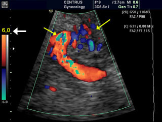
Here is an example of what color doppler blood flow display looks like on an ultrasound display image: